VS-06
VS-06: Technical Specifications
What Is a Liquid Piston ?
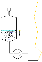
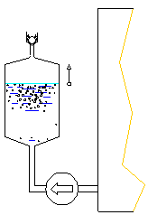
The liquid piston is created by rising and falling oil level due to the cyclic operation of robust gear pump.


The first stage (evacuation) is schematically shown on the left. The oil is drawn from the apparatus by the gear pump.The sinking oil level acts as a piston and creates the basic vacuum necessary to separate gases and vapours from the oil into the void.
The second stage (compression) is schematically shown on the right. The run of gear pump is reversed and the liberated gas-vapour mixture is gradually compressed by rising oil level (upward motion of liquid piston). When the pressure rises, at first the condensation of oil vapours takes place (only this way can be guaranted "no-impact on oil properties" - condensing light fractions are automatically mixed back in the oil) and then are the gases relieved via non-return valve into atmosphere. This process continues until the whole apparatus is filed with oil, then is the gear pump switched on into direct run again and new evacuation stage begins.
How Are Vapours And Gases Separated From Oil ?

Vacuum, temperature and large interfacial area are essential for efficient separation.
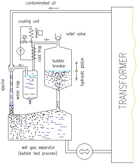
Contaminated oil from transformer is locally adjusted to an optimum temperature and hot oil is under vacuum mixed via ejector with the gas (previously separated from oil) to produce bubbles with a large interfacial area (bubble bed).
The intense diffusion of moisture from oil is enhanced by minimizing the partial pressure of water vapour. This is achieved by sub-cooling the carrier gas to condense and freeze-out all traces of moisture prior to mixing with the contaminated oil.
Dissolved gases and vapours diffuse into bubbles which are then agglomerated, collected and breaked.
The water vapours is collected as an ice in the cold trap, periodically defrosted and collected as a liquid in the water trap.
Note that only a simplified schematics is shown here for clarity.
For more detailed analysis of advantages / drawbacks of existing dehydration (degasing) methods See Maintenance of wet power transformers
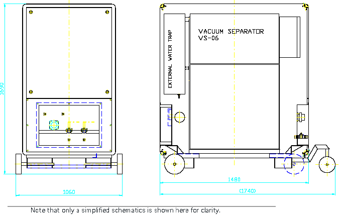
Dimensions & Specification

| Power supply voltage | 400 V (or on request) |
|---|---|
| Power supply frequency | 50 Hz (or on request) |
| Power consumption: | |
| without oil heater | 850 W |
| with oil heater PO-01 | 6200 W maximum |
| Oil throughput | 10 m3 per day maximum |
| Outlet water content | 10 ppm nominal , 4 ppm minimum |
| Outlet gas content | 1% nominal, 0.3 % minimum |
| Outlet filtering grade | 1 µm |
| Weight - universal version (separator, heater ultrafilter, external water trap) | |
| Dry weight ( without oil) | 520 kg |
| Operating weight (oil filled) | 580 kg |
| Hydraulical connection | 2 x flexible 1/2" hose |
| Communication: | faxmodem, GSM modem or LAN link |
For more details See ARS-ALTMANN Presentation 2005, VS-06 CLIMABOX.
