ADT Compact 2003
ADT Compact 2003: Technical Specifications
What Is The ADT Technology ?
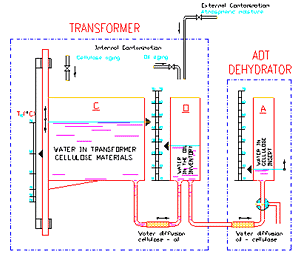
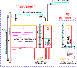
The principle of ADT Dehydrators is based on the cyclical change of two regimes - saturation and regeneration. Both regimes are schematically shown in FIG.2 and FIG.3 as a hydraulic analogy to real water transportation in the system transformer - dehydrator.
The first (saturation) regime is schematically shown in FIG. 2.
The equivalent water content in the cellulose materials of the transformer (C-tank), is higher than the water content in the oil inventory of the transformer (O-tank), the water spontaneously diffuses from cellulose into oil.
If at the same time the water content in the oil inventory (O-tank) is higher than the equivalent water content in the cellulose insert of ADT Dehydrator (tank A) the diffusion process transports the water from oil inventory to the filter insert in the same way.
This spontaneous drying process (the oil is dried by adsorption on cellulose fibres) is very efficient. Moreover, no power input is principally necessary for the transportation of the water diluted in the oil on level ppm (part per million = 0.000 001) at level of % ( 0.01) representing the average water content in the given filter insert.
The water content in ADT filter insert rises and the saturation regime continues until the desired saturation level is reached.
Then the saturation stage is stopped and the ADT Dehydrator automatically proceeds to the second (regeneration) regime shown in FIG.3.
In the regeneration regime, the first step is to stop the water transport between the transformer and ADT Dehydrator. In the following drying procedure the accumulated water is removed from the filter insert.
In the hydraulic analogy the drying process of the filter insert (FIG.3) is purposely reduced to a single turnover of the three-way valve in the bottom of the tank (A) and the discharge of the accumulated water from the tank into the surrounding.
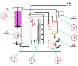
The ADT Dehydrator hydraulic circuit is shown in FIG. 4. The saturation process is simple - the gear pump forces oil from the transformer through the filter insert and the oil with the much lowered water content is returned to its oil inventory.
In the beginning of the regeneration regime the oil inflow from transformer is stopped and the oil is only drawn from the apparatus by the gear pump (11) and forced back into the transformer.

FIG.4 Hydraulic circuit of ADT Dehydrator
Note that only simplified scheme is shown in FIG.4 for clarity
The sinking oil level in the main chamber (1) acts as a piston and creates the basic vacuum necessary for separating moisture from the filter insert (15).
The residual oil in the apparatus is heated up by heater (3) and the filter insert is flushed in a vacuum with the mixture of hot oil and gases from the mixing chamber (2).
Only the gases previously separated from the oil are used for flushing while excess gases are safely relieved via the exhaust valve (61) into the surroundings.
The liberated water vapours are, under a normal surrounding temperature, condensed in the condenser (5) and collected as a liquid in the water trap (4).
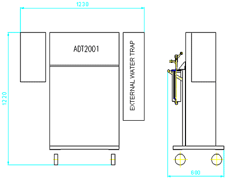
Dimensions & Specification
| Power supply voltage | 400 V (or on request) |
|---|---|
| Power supply frequency | 50 Hz |
| Power consumption: | |
| Saturation regime 200 W | |
| Regeneration regime | 2200 W |
| Oil throughput | 5 m3 per day (max) |
| Outlet water content | |
| nominal | < 10 ppm, |
| minimum | 1 ppm |
| Outlet filtering grade | 1µm |
| Weight - Compact version | |
| Dry weight | (without oil 153 kg) |
| Operating weight | (oil filled) 182 kg |
| Hydraulic connection | 2 x flexible 3/8" hose |
| Communication: | faxmodem, GSM modem or LAN link |


