S-03
S-03: Technical Specifications
- Technical Specifications
- Installation
- Structure and function of the S-03 filter unit
- An example of the standard application
Technical Specifications
| Motor: |
Type :3-phase, squirrel-cage (or on demand) Power: 0.18 kW Voltage: 3x400V, 50Hz (60Hz) (or on demand) Speed: 1350 1/min. Protection class : IP65 (fully hermetized) |
|---|---|
| Oil pump: |
Gear pump (Monobloc version) Hydraulic power : 250 l/hour |
| Safety valve | Adjustable: 3b |
| Filter insert |
Type : B-005-OK-250BP (dia 150) Material: Cellulose (pre-dried at 0.2 % mass weight) Filtering grade: 3 µm Typical pressure drop at 20C: New insert : < 2 bar (3 bar) Max. storage time : 12 months, with undamaged package |
| Pressure / flow reading | Gauge (-100, 300 kPa) |
| Noise | < 65 dB(A) |
| Weight (without oil) | 34 kg |
| Connection | Hose 3/8“ , hard tubing 3/8“ |
| Surface protection | all-stainless |
Installation
The schematical lay-out of the installation of the S-03 filter unit on a tap-changer is shown at Fig.1 .
The S-03 filter unit is usually fixed directly onto the main tank of a transformer.
The hydraulical interconnection between the tap-changer and the S-03 unit is performed by 3/8“ hoses or 3/8“ seamless tubes.
For the detailed description of the installation , power supply and the replacement of the filtration insert See:
www.ars-altmann.com / News / Manuals.
Structure and function of the S-03 filter unit
The contaminated oil from the bottom of the tap-changer is fed into the S-03 unit by the inlet screw coupling and forced by the monobloc gear pump into the vessel where the special large-volume cellulose filter insert is situated.
The water and particles are removed from the oil due the radial flow of the oil through the filter insert, and captured in/on cellulose fibres. The clean oil leaves the S-03 via outlet screw connection and flows back into the upper part of the tap-changer.
The replacement of the saturated filter insert is very simple and can be performed under normal operational condition of a transformer.
For a detailed description of the filter insert See S-03 Manual.
An example of the standard application
An example of the standard application – the triple S-03 system - the three S-03 filter units on the common frame for the simultaneous filtration of three tap-changers of the 60 MVA main transformer.
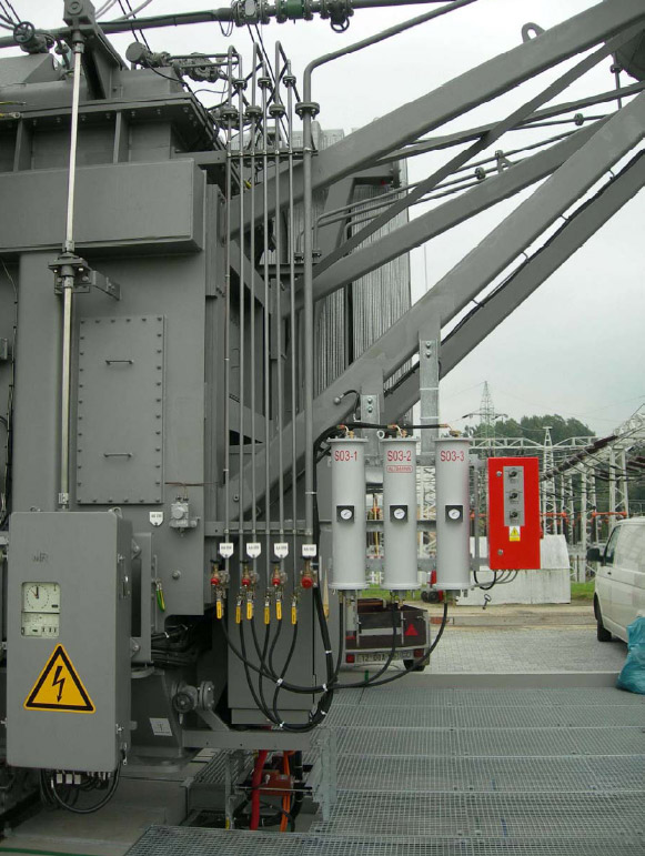
The hydraulical circuits are performed by pressure hoses with a minimal intervention into the existing oil system of tap-changers. Every tap-changer has here its own S-03 filtration unit.
Downloads
S03 Information - Printer friendly version [PDF Document]