Content
- 1. Economical effects of the operational maintenance of a transformer
- 2. Estimation of the economical effect of the postponned replacement of a transformer
- 3. SINDRET (Saving Induced by Deferred REplacement of Transformer)
- 4. Costs of the transformer dehydration
- 5. Costs of the long-term reduction of the oxygen content in the oil
- 6. Costs of transformer "detoxication"
- 7. Saving/ cost relation by different replacement strategies
- Full Document
1. Economical effects of the operational maintenance of a transformer
The potential savings induced by the operational maintenance are most often considered secondary because the main goal of this procedure is always the qiuck restoration of desired parameters e.g.
dielectric strenght of the oil Ud (kV / 2.5mm)
or water content in the oil Qw ( ppm ) etc.
The predominant reasons for the operational maitenance are therefore the legal nature - the transformer may not be operated outside IEC norms.
On the other hand, the main goal of the preventative maintenace is dominatly the saving induced by the prolonging of the life-span of the old or aged transformer , which will be without these measures "sentenced to death" and a new one must be bought. Increased safety of the life-extending operation is evident.
Read next: 1. Economical effects of the operational maintenance of a transformer
2. Estimation of the economical effect of the postponned replacement of a transformer
The benefit of extending the life of a transformer by n years is realized at the end of its normal life.
The minimum benefit is equal to the deferred interest on an expenditure (an investment) E which would otherwise be required to refurbish or replace the old transformer.
The investment E is deferred for n years (by extending of the life-span of existing transformer) and by the given annual Interest Rate IR can be the potential savings S calculated as follows:
S = E [ (1 + IR ) n - 1 ]
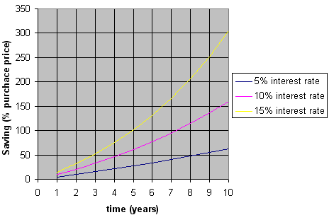
Fig. 1 The potential savings as a function of interest rate and time
The time-related savings for different IR-values are shown at Fig. 1.
Example:
The price of the new transformer is E = € 300 000.- , the existing old one is completely depreciated and for simplicity we suppose that the price level for new one remains virtually constant for future *1
The interest rate is IR = 15 %
Let suppose that the preventive maintenance and the present state of the transformer allows to extend its life-span for min. another % years (n = 5)
S = 300 000 [ (1 + 0.15 ) 5 - 1 ] = 303 407 .-
The potential saving € 303 407.- is enormous, we can save more than 100% of the purchase price of the new transformer in only 5 years.
Fig.1 shows that in fact we can save more than 100% of the price of the new unit in only 5 years.
Used IR = 15% looks high, but please do not forget that our IR-rate should be expected not only as the interest rate of the bank, but more as the revenue rate of our own company ( and a company with the revenue rate under the interest rate of the bank is, from the economical point of view, simply absurd).
A similar picture gives us a 10% interest rate:
S = 300 000 [ (1 + 0.1 ) 5 - 1 ] = 183 153.-
Fig.1 shows that we can, even now, save more than 60% of a purchase price in 5 years.
The life-extending maintenance is a simple technique how to easy, safely and significantly improve the cash flow of any customer - providing that the life-extending maintenance of the power transformers is effective and the costs remain reasonably low.
But to speculate about potential savings makes sense only if we can convicingly demonstrate that our deferred replacement will produce savings de-facto.
The corresponding problem is substantially more complicated due more different parameters. To avoid human errors ARS-Altmann developed the SINDRET ( Savings Induced by Deferred REplacement of Transformer). For more details about SINDRET background See SINDRET Explanation Tutorial.
*1 This premise is not even seriously disturbed by the price increase of the transformers because this increase is mostly slow and linear, but our saving is always of an exponential character.
Read next: 1. Economical effects of the operational maintenance of a transformer
3. SINDRET (Saving Induced by Deferred REplacement of Transformer)
How to use SINDRET: Explanation Tutorial
SINDRET Basic Calculator aims to answer the following question:
- Is it economically efficient to replace a given transformer by a new unit under the given conditions
or vice versa
- Is it more profitable to lengthen the service life of a given transformer under the given conditions within the suitable strategy (e.g. FRS - Flexible Response Strategy).
For this purpose SINDRET combines the following:
- Technical and operational relations concerning the old transformer
- Investment conditions expressed by the present and future Interest Rate (IR)
- Technical and economic relations pertaining to the new transformer
- Technical and economic relations concerning the methods enabling to lengthen the service life of the old transformer
into the form which, by stating the expenses and costs growth over the time, shows the economic efficiency of the chosen strategy, and also reveals its technical feasibility in order to reach the required service life of a given unit.
Technical relations describing the old transformer are expressed in the form of an expert's report - e.g.:
The time-trend relations show the increasing ageing of the cellulose insulants.
Residual Life Expectancy is max. 5 years under present conditions.
The transformer should be immediately dehydrated to increase the dielectric over 60 kV/2.5mm and then continuously degassed and/or hermetized to reduce an ageing process in the solid insulants.
The technical expert examination of mainly larger units is added by the reports of the DGA (Diluted Gas Analysis) and the changes of the furan content in oil.
The results of the expert examination always show the Residual Life Expectancy and other important information specifying which methods of treatment should be employed (the transformer is wet and should be dried).
SINDRET operates with the estimate of the Residual Life Expectancy at three basic levels (high, medium, low) indicating that the given transformer can be operated (after 10, 5, 1.5 years of use) as before until it fails.
Technical and economic relations concernig a new transformer must be provided by the supplier of the new unit. The given specifications for a given unit (40MVA) must contain:
| Purchase price PP (€) | 320 000.- |
| Total Replacement Costs (TRS) | 390 000.- |
Lower losses of a brand new unit constitute one of the primary reasons of the transformer exchange. After installing the new unit the customer can buy or make use of more electricity which would be lost in the form of heat when continuing to use the old unit.
In order to compare the operating costs of the transformer in process and a brand new unit under the given working conditions, we must input other parameters into the following table
| Transformer | current | new | |
|---|---|---|---|
| No-Load Losses | NLL (kW) | 12 | 10 |
| Load Losses | LL (kW) | 112 | 82 |
| Operational Hours | OH (hr / year) | 8700 | |
| Loading Rate | LR (%) | 30 | |
| Electricity Sale Price | EP (€ /kWh) | 0.04 | |
where:
| NLL | ... | No-Load Losses ( so called steel or iron losses) |
| LL | ... | Load Losses (loss in conductors at the max. transformer load - so called copper losses) |
| OH | ... | Number of working hours per year |
| LR | ... | Transformer load coefficient (%) --> LR = 100 for max. load |
| EP | ... | Electricity Sale Price to a customer |
Annual No-Load Losses = NLL x OH (kWh / year)
Annual Load Losses = LL x OH x (LR/ 100)2 (kWh / year)
and with the help of the available data, we can obtain the rate of differential savings per year:
- Δ NLL = ( Annual No-Load Losses of an old unit - Annual No-Load Losses of a new unit) x (kWh price) / purchase price of a new unit
- Δ LL = ( Annual Load Losses of an old unit - Annual Load Losses of a new unit) x (kWh price) / purchase price of a new unit
The use of Δ NLL and Δ LL values is essential as they are given as relative annual saving costs pertaining to the purchasing value of a new unit (% of purchase price of a new transformer / year), are therefore of the same character as the annual interest rate.
To put it differently - the sum of the values give us so called relative differential
loss RDL:
RDL = ΔNLL + ΔLL
which enables to observe directly the potential
gain achieved by the old-new unit loss difference with the interest rate (IR
) considered for the future investment, i.e. the purchase of a brand
new unit.
Subsequently, we can make the decisions:
| RDL >> IR | ... | relative losses are a lot of higher that the interest rate (the annual price of the dissipated energy is lot of higher than the adequate payment of the interest rate for the new transformer) old transformer should be replaced as soon as possible |
|---|---|---|
| RDL ~ IR | ... | relative losses are approx. the same as the interest rate, decision about replacement versus life-extending has to be based on other criteria |
| RDL << IR | ... | relative losses are a lot of lower than the interest rate, application of life-extending methods allows considerable savings |
For a reasonable economic decision it is always necessary to colate and process a relatively large amount of information gained from at least five sources:
| Bank (and/or your investment department) | ... | Interest Rate (IR) |
|---|---|---|
| Supplier of new transformer | ... | No-Load Losses (NLL), Full-Load Losses (FLL), Transformer Purchase Price (PP) |
| Client (old transformer) | ... | NLL, FLL, Operational Hours per year (OH), Loading Rate (LR), Total Replacement Costs (TRC) etc. … |
| Supplier of electricity | ... | Electricity Price in situ (EP) |
| Diagnostic | ... | Residual Life Expectancy of aging transformer (RLE) |
The basic parameters of aging and new transformer (NLL and FLL) are constant , but the other parameters as a IR, EP, OH, LR or RLE may be highly volatile.
It is always necessary therefore to specify long-term projections of potential changes of RDL versus IR.
To limit potential (human) errors, ARS-Altmann have developed a special freeware SINDRET .
The first window of SINDRET enables easy input of all these parameters and all required calculations will flow from this including the time related savings.
In this case it can be seen quite clearly, that the deferred replacement of the old transformer is profitable – we can save ca € 52 000.- ( or 16% of the purchase price of the new transformer) over the next five years.
Sound economic analysis is, almost exlusively, essential before proper management assessment can be taken.
For future profitable transformer operation the relationship RDL << IR should be seen as the only reasonable and proven basis for the management discussion and the subsequent selection of life-extending methods for aging transformers.
Please do not forget - the main factor which can strongly affects the savings is TRC (Total Replacement Costs). The TRC represents here the complete costs of the transformer replacement, e.g. disassembling, environment-friendly disposal of the old unit inclusive the disposal of an aged oil , potential rearrangement of the location, installation of the new unit, transportations - logistics, etc.
Rough estimate of TRC = (1.5 - 2) x PP … i.e. transformer replacement total costs can vary between 150 - 200% of the Purchase Price (PP) of the new transformer .
On the contrary , transformer treatment costs
(See :
The costs of dehydration,
The costs of the long-term reduction of the oxygen content in oil
and
The costs of the transformer detoxication )
represent the relatively
well-defined items, because they should be always stipulated and quaranted
by the producer
(provider) of the life-extending technology.
In SINDRET are costs of the transformer treatment always and strictly divided into:
- Treatment Purchase Price - total purchase price of a given technology (or the combination of selected technologies) , which basically represents the investment item.
- Operational Costs – electricity supply, maintenance, monitoring, exchange of adsorbtion or filter inserts , etc.
For particular examples of the use of SINDRET click on Calculation Examples [PDF] (available only in German language at the moment, english version will be published shortly).
Back to the SINDRET Calculator
Read next: 4. Costs of the transformer dehydration
4. Costs of the dehydration of a transformer
4.1 Off-line transformer dehydration
For the treatment is a transformer always shutt. Preliminary work takes usually 1-2 days with regarding the size and operational voltage of transformer and used methods (e.g. dismantling of bushings for Oil Spray …), and can therefore be relatively very expensive (extra manpower, oil tanks, cranes….).
The treatment generally non-reversibly removes water, gas and particles from the oil inventory of the transformer . But the effective drying of the cellulose insulants can be done only when the oil inventory of the transformer is discharged and then the vacuum interacts with the hot cellulose insulants directly.
The costs of all dehydration methods is a very rough estimation of the cost of the removal of 1 kg water which can strongly vary with local conditions.
Economical Goals: Table E1| Method | Advantages | Draw-backs | Costs: € / kg water |
|---|---|---|---|
| Vaccum Oil Drying |
|
Only oil invetory can be effectively dried * | ? |
| Oil Spray |
|
|
min. 370 - 500 |
| LFH Method Low Frequency Heating Method |
|
|
min. 300 - 500 |
* By the treatment the oil inventory of a transformer is not discharged. The oil is heated over 80C and the water is removed from the oil by means of external high vacuum drier. Because the diffusion coefficients between the paper (boards) and oil are always very low and the time-period of the treatment is usually too short (days), the paper and especially the boards cannot be effectively dried. Don´t forget - there is always more than 95% water in the solid insulants and only 5% or less is solved in the oil.
** tBoards and other high density cellulose insulants of a transformer can be heated by repeated discharge of cold and recharge of hot oil inventory but this process prolongs the drying process and increases the costs dramatically
4.2 On-line transformer dehydration
The transformer remains on-power , no special adaptations on the main tank are necessary. The installation of the drier is very simple and can be done by one man without troubles within a hours.
The costs of all dehydration methods is a very rough estimation of the cost for the removal of 1 kg water which can strongly vary with local conditions especially with the operational temperature of the transformer.
Economical Goals: Table E2| Method | Advantages | Draw-backs | Costs: € / kg water |
|---|---|---|---|
| Vaccum Oil Drying |
|
min. 120 - 250 |
|
| Adsorption process |
|
|
min. 250 ** |
* The very dangerous loss of clamping forces induced by the overdrying of the cellulose insulants can be today effectively controlled by:
- on-line measuring of the volume of removed water
- on-line measuring of the noise spectrum of the transformer
** BThe costs of column replacement (if molecular sieve is exhausted) can be substantially reduced by the external high-temperature regeneration(dehydration)
*** By the permanent application of the high vacuum / high temperature are removed (stripped) from the oil not only water and gases but its light fraction as well. Chemical composition of the oil can be changed in this way. This process can be effectively suppressed. See - Liquid Piston Principle - / Product Range / VS-06
**** See Product Range / VS-06
**** See Product Range / ADT
4.3 Economical comparison of existing on-line drying methods
The costs of transformer dehydration depend on:
- selected technology
- duration of dehydration treatment or number and size of dehydrated transformers
- the arragement made to acquire the dehydrator
As mentioned there are three basic on-line methods and apparatus:
- small vacuum drier . e.g. Vacuum Separator VS-06
- adsorption drier whose adsorption cartrige(s) must be routinely changed
The purchase of the drier is usually the most economical, especially if there are several smaller units to be maintained at acceptable moisture levels in a preventative maitenance program, or we have a large units which have to undergo a lengthy corrective or even continuous life-extending treatment.
The main cost components of the dehydration are therefore:
- purchase price
- installation cost
- operational cost (energy , routinely exchangeable items, labour costs, transportation etc.)
Installation costs are for both driers approx. the same and can be excluded from the comparison.
A typical cost comparison is showed as an example in folowing figure. The costs are expressed as a function of the amount of water which have to be removed.
Economical Goals: Boundary conditions| Drier | Purchase price € |
Operational costs € / kg water |
|---|---|---|
| Vacuum drier | 60 000.- | 120.- * |
| Adsorption drier | 25 000.- | 700.- ** |
* the operational cost = power consumption
** the operational cost = power consumption + purchace price of changed cartridges + labor costs + transportation (estimation)
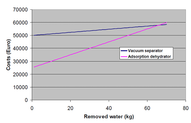
Fig. 2 Comparison of the costs of on-line drying methods
At the first sight it seems that dehydration by the vacuum method is much less advantageous than an adsorption one. The cost break-point No.2 comes not until after removing of ca 66 kg water or ca 3-4 years of the operation.
In this case we would be comparing the incomparable.The vacuum drying is, in contrast to the absorption, an ultimately complex process which can successfuly remove all main transformer enemies - water, gases and particles.
4.4 Conclusion:
When the problem of the aged transformer is strictly limited to a higher content of the water in the cellulose insulants (and increased amount of particles) the proper, sufficient and the most economical solution is the on-line drying by absorption drier.
But mostly the problem is not so simple, because for the extending of the life-span of transformer we must not only "discharge" the undesired aging products (water, acids and particles)from its insulation system, but control the internal conditions that the aging process would be permanently and strongly reduced or stopped in future.
The simplest way to stop the oxidation aging of the transformer is a passive or active longterm reduction of the oxygen content in the oil and decreasing of operation temperature of given transformer.
Read next: 4. Costs of the transformer dehydration
5. Costs of the long-term reduction of the oxygen content in the oil
5.1 Passive systems
The up-grade costs can strongly vary with local conditions and with the type and size of the transformer
Economical Goals: Table E3| Method | Advantages | Draw-backs | Up-gradeCosts € / MVA |
|---|---|---|---|
| Sealed-Tank Type |
|
|
? |
| Gas-Oil Sealed Type |
|
|
250 - 350 |
| Automatic Inert-Gas Pressure Type |
|
|
150 |
| Bag-In Tank or Membrane-In Tank Type |
|
|
300 - 500 |
| TRAFOSEAL |
|
< 100 |
* The old conservator must be removed and a new- or modified one must be installed
** The automatic inert-gas pressure apparatus must be installed
*** The old conservator must be removed and a new one equipped by the bag or membrane must be installed
5.2 Active systems
In principle every small vacuum drier can be used as a active degassing device which is simply connected e.g. to the Filter Press Connectors of the main tank. The goal is to reduce the oxygen content permanently under 4000 ppm - it slows down the aging ca 4 - 5x compared to the full saturation ( O2 ~ 22 000 ppm)
Economical Goals: Table E4| Method | Advantages | Draw-backs | Costs € / unit |
|---|---|---|---|
| Small vacuum drier |
|
|
10 - 15 000.- |
| Vacuum separator VS-04 |
|
|
25 000.- |
5.3 Combined systems
Only four combinations of passive-active systems are possible - the following cost estimation is valid for ca 100 MVA Transformer.
The goal is to reduce the oxygen content permanently under 1 - 2000 ppm - it slows down the aging by ca min. 10x compared to the full saturation ( O2 ~ 22 000 ppm) .
Economical Goals: Table E5| Method | Advantages | Draw-backs | Costs € / unit |
|---|---|---|---|
| Small vacuum drier & Bag-In Tank or Membrane-In Tank Type |
|
|
Min. 45 000.- max. 60 000 |
| Vacuum separator VS-04 & Bag-In Tank or Membrane-In Tank Type |
|
|
ca 65 000.- |
| Small vacuum drier & TRAFOSEAL |
|
|
Ca 25 - 30 000.- |
| Vacuum separator VS-04 & TRAFOSEAL |
|
ca 35 000.- |
Read next: 4. Costs of the transformer dehydration
6. Costs of transformer "detoxication"
The reclamation & desludging costs can strongly vary with local conditions and with the type and size of the transformer.
Economical Goals: Table E6| Method | Advantages | Draw-backs | Costs: € / kg oil |
|---|---|---|---|
| Change of oil inventory NN < 0.1 |
|
|
ca 0.8 - 1.- |
| Reclamation of oil inventory NN < 0.3 Short -term by-pass process |
|
|
0.5 - 0.8 .- |
| Reclamation of oil inventory & desludging long -term by-pass process NN < 0.5 |
|
|
ca 0.8 - 1.- |
| Reclamation of oil inventory & radical desludging long-term by-pass process NN > 0.5 |
|
|
ca 1 - 2.- |
* valid for an ca 40 MVA-transformer, 13 m3 oil, reclamation apparatus with oil throughflow min. 4 m3 / hour
Read next: 4. Costs of the transformer dehydration
7. Saving/ cost relation by different replacement strategies
7.1 Introduction
The replacement of an old transformer mostly represents only troubles. The direct (purchase price) undirect costs are relatively very high and the motivation to act is low, because the planned replacement is virtually fruitless. A new unit makes mostly the same job and its efficiency is usually only a bit higher than the old one (the iron and copper loss is usually only a bit lower) - therefore operational costs of a transformer cannot be markedly reduced.
Generally there exist three basic strategies for the replacement of an old transformer:
- A NamePlate Strategy (NPS)- the transformer is replaced immediately after the expiration or its nameplate age
- a Don't Care Strategy (DCS)- a careless manager accepts growing hazard conditions, makes nothing and hopes the best
- a Flexible Response Strategy (FRS) - the manager analyses all existing conditions and risks and flexibly optimizes the approach by the comparising the existing and potential hazard levels versus savings / costs relation
The example of the economical effect of the different strategies is shown as a RTS (Relative Total Saving) in the following picture:
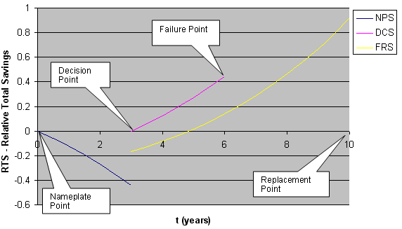
Fig. 1 general comparison of economic effects of different strategies
7.2 NPS - NamePlate Strategy
The origin of the X-scale (Nameplate Point) is equivalent to the nameplate age of the transformer. Nameplate Point (t = 0) means the replacement of the old transformer and the installation of the new unit according to the nameplate strategy.
Let us suppose that the condition of our transformer is in a relatively good shape, no extremely deterioration symptoms are evident and therefore no special treatment is necessary.
The blue curve then shows a negative Relative Total Saving (1) in a time-period Nameplate Point - Decision Point
(1)
RTS = -1 * [((1+i)n-1)-((ΔNLL + ΔFLL)*PP)/TRC)*((1 + i)n-1)/i]
- RTS ... Relative Total Saving = Total Saving / TRC
- TRC ... Total Replacement Cost = Purchace price (PP)
- + removal cost of old transformer
- + local conversion cost
- + general logistic cost
- Δ NLL ... cost decrement is equivalent to reduction of No-Load (iron) Losses as a % of Purchace price (PP) per year *
- Δ FLL ... cost decrement is equivalent to reduction of Full Load (copper)Losses as a % of Purchace price (PP) per year *
- I ... Interest rate
- n ... years
Fig. 1 shows a RTS = RTS (t) relation for: TRS = PP, i = 0.15 , n = 3 ( time- period Nameplate Point - Decision Point), ΔNLL = 0.006 PP, Δ FLL = 0.02 PP
* See Transformer Life-Cycle Cost
(http://64.90.169.191/applications/electrical/energy/trans_life_cycle.html)
In our example NPS means minimal loss 0.42 TRS for a time-period Nameplate Point - Decision Point
The new transformer is installed even though the old one has been working well. Strictly from the point of the cash flow, the responsible manager is not-our-company-man but a transformer-producer-man. A transformer producer benefits from the company potential saving achieved by the postponed purchase of a new unit.
7.3 DCS - Don't Care Strategy
Let us suppose that after exceeding the Nameplate age, aging symptoms of the transformer gradually increase and during the following 3 years the monitoring has shown an increased deterioration of the transformer - we should take measures. See Decision Point (Fig. 1).
The magenta curve then shows a positive Relative Total Saving (2) in a time-period Decision Point - Failure Point.
(2)
RTS = ((1+i)n-1)-((ΔNLL + ΔFLL)*PP)/TRC)*((1 + i)n-1)/i
the equation is the same as a equation (1) only the sign is opposite.
DCS strategy is simple but stupid - the DCS manager does nothing and lets the transformer operate without any adequate maintenance until its failure - See Failure Point.
The owner then faces substantial replacing or refurbishing costs:
- minimum cost of a transformer failure can be as five times the cost of the new unit
- cost of a non-catastrophic failure can be as high as twenty times the price of the unit
- cost of all collateral effects of a catastrophic failure can exceed hundred times the cost of the unit
The DCS manager has ponentialy saved 0.42 TRC from the Nameplate Point to the Decision point and another ca 0.4 TRC from the Decision Point to the Failure Point, but
the potential loss induced by the failure is always much higher than any potential savings
The DCS manager not-our-company but an insurance-man. In the event of a non- or catastrophic failure the insurance company will succesfully argue that the basic security criteria had been systematically neglected and refuse the indemnification.
It is evident that the both mentioned strategies (NPS) and (DCS) are principially wrong and expensive.
The responsible manager is always a FRS manager as clearly shows the Fig.1
7.4 FRS - Flexible Response Strategy
The Relative Total Saving (RTS) corresponding to FRS can be expressed as follows:
(3)
RTS = (1-LEC/TRC) * ((1+i)n-1)-((OLEC+(ΔNLL + ΔFLL)*PP)/TRC)*((1 + i)n-1)/i - LEC/TRC
where:
- LEC ... Purchase price of all used Life-Extending Technologies
- OLEC ... Operational cost of Life-Extending Technology
Fig. 1 shows that a well selected and properly operated life-extending technology ( yellow curve) can safely prolong the transformer life-span for another 7 years or more.
FRS potentialy saves 0.4 TRC from the Nameplate Point to Decision point, then the life-extending technology is bought and another ca. 0.9 TRC from the Decision Point to an expected Replacement Point can be saved but
in contrast to DCS
under determined, secured and fully controlled operational conditions.
(FRS) strategy shows potentially the highest gain, but is more sophisticated.
At first the manager must collect all neccessary information, not only about the given transformer, but also about all available life-extending methods.
For him it is most difficult to decide what life-extending technology should be used and what potential advatages could be achieved. The problem is that the manager is usually not a real professional in the life-extending area. The replacement of the old transformers is usually an occasional job for him, but
the optimized FRS conception always means a tailor-made solution for a specific transformer.
Therefore SINDRET (Savings INduced by Deferred REplacement of a Transformer) provides the first help for a FRS manager.
2003 - 2026 © ARS Altmann Group. Altmann ®
is a registered trademark.
webdesign by www.2tags.com